Thanks… I really appreciate your sentiment and explanation. With respect to lubrication, Dave from Arizona CNC suggested that I use as little grease in the bottom bearing as possible. I used a syringe to put a tiny bit of grease between each roller. I then placed the roller section (cone) of the bearing in the outer race and used my finger to rotate the inner race with respect to the outer race for about 12 revolutions. I turned the bearing over to inspect and was amazed to find a bunch of grease expelled out the bottom. I used a small dental like tool to remove any excess. The result was an even coating on all the rollers etc. I believe there is enough grease, but not too much.
While I purchased a press to install the new bearings, I did not use it. I will post the method I used shortly as I think it offers a bit more control.
I am indeed getting ready to start cutting parts shortly but have one small hurdle. I am working on two small servo issues at the moment. One is that I am feeding the AC servo a 0-10 volt analog signal, but the motor does not run at its max of 3500 rpm with a 10 volt input. I’m checking through the manual now as I think this is a programming parameter. Secondly, I’m trying to educate myself with respect to fine tuning the servo (This is all new to me). The splined spindle is driven by a splined pulley. There is a bit of slop between the splines. I can actually hear the slop if I rotate the spindle back/forth by hand. I mention this because when I slow down the spindle, I hear a bit of a tapping sound. I think what I am hearing is the servo overcompensating as it decelerates due to poor tuning, and I believe the tapping sound is coming from the slop in the splines as the spindle jitters as it decelerates. You got to love this stuff!
There is unfortunately a lot of slop between the spline shaft and hub, which is why I had to put the encoder directly on the splined shaft for my rigid tapping upgrade. A couple suggestions:
Operate the servo motor in Speed Control mode (vs. Position or torque)
Reducing the Proportional gain during tuning might decrease the system’s sensitivity to the backlash
I found an auto tune parameter. This parameter adjusts the rigidity of the system by changing a group of parameters together. The default setting was 13, I changed it to 7 and eliminated 80% of the rattling sound from spline/hub interface. It is good enough to start milling now.
The JMC manual is not bad, but for someone with no previous servo tuning experience, it is a bit challenging. I could not figure out how to adjust the Proportional gain as noted above. Perhaps they are using a different term for the same. I am going leave this for now, and revisit using tuning software in the future. I am still working on the max rpm issue.
With respect to installing the spindle bearings, here is my approach. My goal was to avoid using the press if possible. Here it is:
Heat the inner race/roller cage (also called the cone) of the bearings in the oven to 155. I baked them for an hour. I also wrapped them tightly in tin foil to minimize dust.
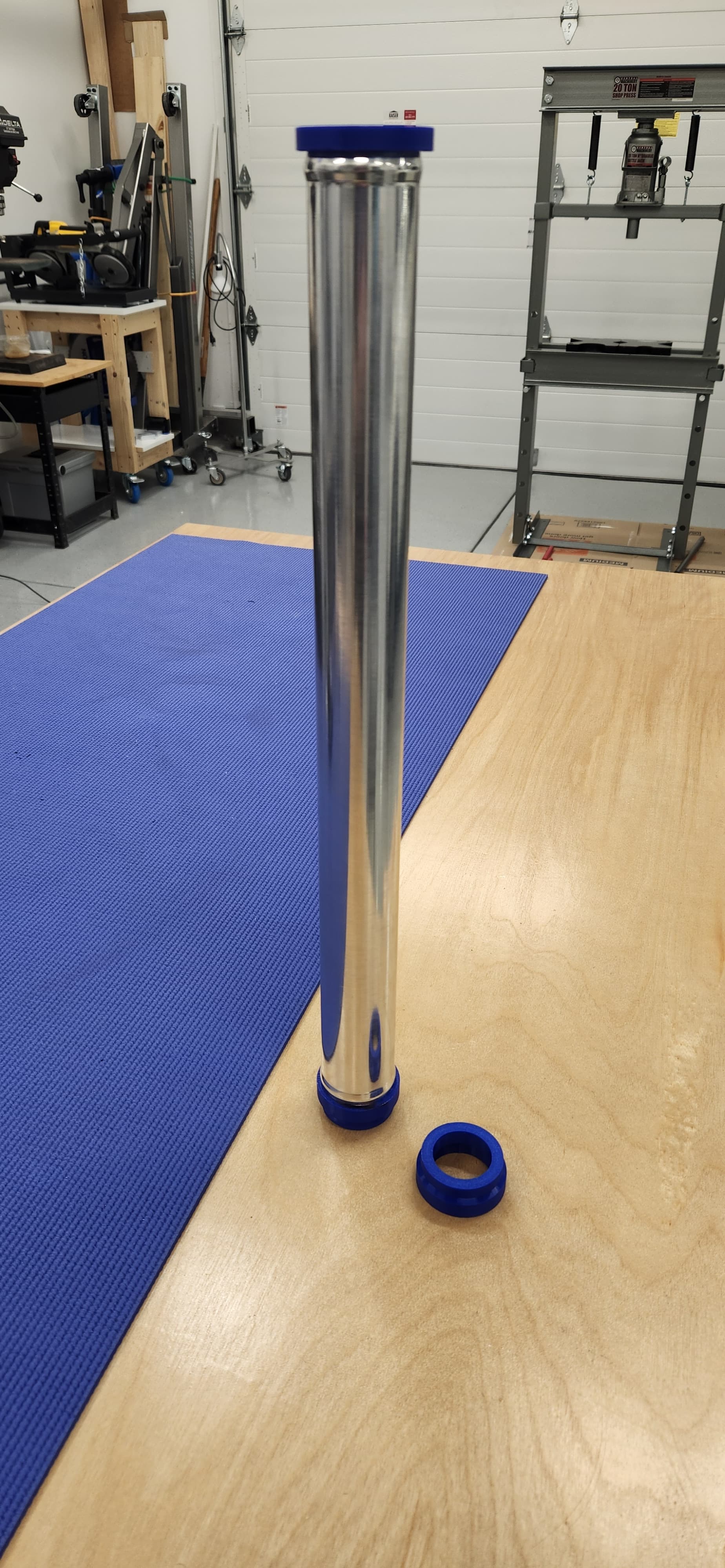
I then used a tube (https://www.amazon.com/dp/B0BR91H84R?psc=1&ref=ppx_yo2ov_dt_b_product_details) which fits over spindle and a 3d printed adapter that mates the tube to the inside race of the bearing. I printed one adapter for the top bearing and one for the lower bearing. I also 3d printed a plug to fit into the top of the tube, to allow me to hit the top of the tube squarely with a 2# dead blow hammer. I was then able to tap top of the tube and drive the bottom bearing until I felt it hit the shoulder. I was able to drive it fairly easily since the bearing was heated and the spindle was frozen. I placed the spindle with the bottom bearing installed through the quill and tapped the top bearing just until it almost touched the corresponding inner race. That’s it. Then I tightened the spindle nut just to the point that the endplay was zero. Done! I really like this approach because it gave me complete control over exactly how far I drove each bearing and race. Even better, I get to return this large press that is taking up too much floor space!